Monday, April 2, 2012

Serkan Orhan, 030070165, 6th Week part2

2)Roller Conveyor (Group:Production Line)
[Old]

This type of conveyor is used to transport various shapes of products such as boxes or materials which extend over several rollers. This type consists of cylindrical rollers supported in frames over which materials are allowed to move. They are driven by power or gravity. These are of different varieties and can move material in horizontal direction as well as from the upper floor to lower floor.
These have a long life readily assembled and installed, easy to adjust and used for handling large variety of loads. Load with rigid and smooth base are moved on the roller conveyors. Other items can be moved after placing themon flat boards. Pitch of the the rollers should be such that minimum of 3 rollers must remain under load at all times, spacing is generally kept at 8 cm, 10cm or 15cm.
There are two main type of roller conveyors, with different sub-types:
  • Gravity type or Unpowered type
  1. Stationary
  2. Mobile
  • Powered type
  1. Chain driven
  2. Gear driven
  3. Belt driven
(Arora K.C., Shinde V.V., Aspects of Material Handling, pg.94, Kayra Ermutlu)


[New][Better]

Roller conveyors can be operated with or without power for movement. Usually they are powered with a chain drive for easy movement of material. The rollers are fitted with end sprockets which are in turn driven by an endless chain. The roller conveyors are invariably used for transportation of packages, cartons, pellets or any other packaged material. They are not normally used for unpacked food materials. They consist of a series of rollers fixed on either sides with ball bearings. The rollers are closely placed with a small clearance in between so that each roller rotates independently. While rotating, they transport the carton placed on them. A typical roller conveyor is shown in Figure 26.12 which moves horizontally only. Some roller conveyors are made to turn the movement of the material horizontally as shown in Figure 26.13. Normally. whenever 
we need to change the direction of movement of the packaged material/cartons, either roller conveyors or slat belt conveyors alone are preferred. Roller conveyors have an additional advantage that the moving material is never blocked as long as its size is bigger than the clearance between each roller. Roller conveyors can also be made for movement af the material in the inclined position also both in upward and downward direction (as shown in Figure 26.14). The inclination should be 10°-12° for gravity flow or power driven rollers. Higher degrees of inclination may result in slipping or scaring of the packages. Chain driven rollers can be used for heavy duty operation where the speed of conveying could be as high as 2.5 m/s, whereas belt driven rollers are used only upto 0.25 m/s. They can be fitted with reversible drives so that the material can be moved in either direction. In some conveyors, provision is made for intermediate discharging of material also. 


(Fundamentals Of Food Engineering, Rao, pp. 504-505)


3)Continuous Chip(in Metal Machining) (Group:Chip type)
[Old]
Continuous chips coming out during machining in machine shop. These types of chips are obtained while machining ductile material such as mild steel and copper. A continuous chip comes from the cutting edge of a cutting tool as a single one piece, and it will remain as one piece unless purposely broken for safety or for convenience in handling. Formation of very lengthy chip is hazardous to the machining process and the machine operators. It may wrap up on the cutting tool, work piece and interrupt in the cutting operation. Thus, it becomes necessary to deform or break long continuous chips into small pieces. It is done by using chip breakers. Chip breaker can be an integral part of the tool design or a separate device.
(Introduction to Basic Manufacturing Processes and Workshop Technology,Rajender Singh,p 402)

[New][[Better]
Continuous chips are normally produced when machining steel or ductile metals at high cutting speeds. The continuous chip which is like a ribbon flows (Fig. 2.7) along the rake face. Production of continuous chips is possible because of the ductility of metal (steel at high temperature generated due to cutting) flows along the shear plane instead of rupture. Thus on a continuous chip you do not see any notches. It can be assumed that each layer of metal flows along the slip plane till it is stopped by work hardening. Each of these layers get welded to the previous ones because of the high temperature, thus forming a continuous chip. Some ideal conditions that promote continuous chips in metal cutting are sharp cutting edge, small chip thickness (fine feed), large rake angle, high cutting speed, ductile work materials and less friction between the chip tool interface through efficient lubrication. 
Continuous chips are the most useful chips since the surface finish obtained is good and the cutting is smooth. It also helps in having higher tool life and lower power consumption. However, because of the large coils of chips. chip disposal is a problem. For this purpose various forms of chip breakers have been developed which are in the form of a step or groove in the tool rake face. The chip breakers allow the chips to be broken into small pieces so that they can be easily disposed Off. 
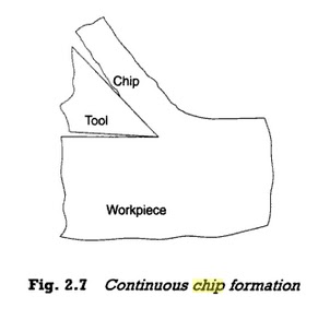

(Manufacturing technology: metal cutting and machine tools,
Posinasetti Nageswara Rao,2006,p. 9)


4)Butt Weld [Group:Manufacturing Method]
[Old]
The butt weld is a connecting weld between plates which is largely free from force flow diversion and hence has a low stress concentration factor.ıt makes a joint in the same plane or only at a slight angle.It has the following variants;square butt weld, single V butt weld, single U butt weld with or without root face, U and V welds also arise as double welds(Double V weld identical to X weld), and the raised edge butt weld.

(Dieter Radaj,Design and analysis of Fatigue Resistans Welded Structures, page 38)


[New][Better]
Butt welds in carbon—manganese steels, made by arc welding with consumables giving weld metal matching the parent metal strength, are as strong as or stronger than the steel itself. In very high strength steels it may not be possible or feasible to produce a weld metal of matching strength and so a weld metal of lower strength than the parent metal may have to be accepted. For most purposes then, a butt weld in common structural steels does not have to be taken into account when calculating the static strength of a structure in the sense that its strength may be considered to be identical to the parent metal. However if ductility, as much as strength, is a necessary property, such as in the plastic design of a beam to column joint, it is necessary to ensure that the whole joint, comprising the parent metal, its heat affected zone and the weld metal, can offer the required rotation of a section up to the specified limit state. This requires attention to the ductility of the weld metal and the ductility of the column flange material in all axes as well as to the design of the weld preparations and welding procedures so as to avoid defects such as lack of penetration and lack of fusion. These matters have a special significance in the case of earthquake resistant designs which demand extremes of ductility at the beam to column joints. The difficulties inherent in achieving such properties have been recognised and proposals have been made for the use of a beam design detail which induces the plastic hinge to occur at a position in the beam away from the welded beam to column joint.

To allow high ductility to be exploited particular attention must be paid to the notch toughness of both the parent and weld metals. This may be particularly important in the case of undermatching weld metals where plastic strain may occur in the weld metal whilst the parent metal remains in an elastic state. 

For welded joints in aluminium alloys, whose strength may be reduced by the heat of welding, the application standards give strengths or factors which have to be used to account for this. 


(Welded design: theory and practice, Hicks, 2001, p.54)


030070094 Buğra Çetinkaya 6th Week Definitions


1) Belt Conveyor (Production Line)

Previous Answer
This type is available in two common forms: flat belts for pallets, parts or even certain types of bulk materials and troughed belts for bulk materials. Materials are placed on belt surface and travel along the moving pathway. The belt is made into a continuous loop so that half of its length can be used for delivering materials and the other half is the return run (usually empty).
The belt is supported by a frame that has rollers or other supports spaced every few feet. At the each end of the conveyor ( where the belt loops back) are driver rolls (pulleys) that power the belt.
(Computer Aided Design And Manufacturing, Lalit Narayan Et Al., p.529)

New/Better Answer
Belt conveyors are most suitable for handling loose bulk materials like soil, earth, gravel, sand and crushed materials. Being continuous in operation, conveyors do not suffer from cycle-time constraints and idle time in operation. They are idle only when they are not in operation or when there is a breakdown or when there is no feed on the running conveyor.
The general construction of a belt conveyor consists of a continuous belt running over two terminal pulleys, one of which is driven by a motor, called the head pulley, and the other, called the tail pulley, rotated by the belt friction. The material to be transported is fed at one end, normally the tail end and transported by the travelling belt, and discharged at the motor-driven pulley or the head pulley. The whole conveyor unit can be mobile, that is, mounted on wheels for easy transportation from one place to other as required.
Belt conveyors, when they are used for bulk materials, are troughed depending on the troughing angle of the idler sets between the two terminal pulleys. The idler sets, arranged at a predetermined spacing, support the load carrying belt and prevent it from sagging and stretching between the two terminal pulleys. The troughing angle increases the cross-sectional area of the material being carried on the belt and, hence, the capacity of the belt for unit time. Belts come in the standard widths of 250, 300, 400, 500, 630, 800, 1,000 and 1,200 mm, and so on. They are made of layers of cotton or synthetic material called plies embedded in rubber. The troughing angle of idler sets is normally 20 degrees which is the angle of the axes of the side rolls to the horizontal. Belt conveyors are specified by their carrying capacity, for example, 50 tonnes of gravel per hour, the belt width in mm, and the troughing angle in degrees.

(Kamaraju Ramakrishna, Essentials of Project Management, p.268)


2) Photodiodes (Type of Photodetectors)

Previous Answer
A photodiode consists of a back-biased p-njunction which, under dark conditions, behaves as a normal back-biased diode. With these conditions the only current flowing through the diode will be the leakage current (typically 1 μA).
Absorbed light will generate electron/hole pairs, and the current through the diode will increase to a typical value of 100 μA. A photodiode has the response that it can be considered as a constant current device with the current determined by the light intensity.
The current/intensity relationship is quite linear and the response is fast; typically 0.2 μs but devices as fast as 1 ns are available. In general, photodiodes are the smallest optical sensor which, in conjunction with their high speed, makes them well suited for fibre optic data transmission and similar applications. Typical operating wavelengths are 8000Å to 11000Å (silicon) and 13000Å to 20000Å (germanium).
The relatively low level current can easily be converted to a high-level voltage using a DC amplifier. The light-dependent diode current flows through R to give an output voltage IR which is directly related to light intensity.
(Parr E.A., Industrial Control Handbook, pg.192, Kayra Ermutlu)
New/Better Answer
Photodiodes arc semiconductor light sensors that generate a current or voltage when the p-n junction in the semiconductor is illuminated by light. The term photodiode usually refers to sensors used to detect the intensity of light. Photodiodes have no internal gain but can operate at much higher light levels than other light detectors. In contrast Avalanche Photodiodes (APD) do have internal gain. The materials used to realize the photodiodes are:
Silicon: It is now the most widely used material for photodiodes. The wavelength range is about 200 — 1100 nm with a peak near 850 nm, at which the spectral responsivity is up to 0.65 A/W and the quantum efficiency is close to 100%
Germanium: The wavelength range of these junction diodes extends further into NIR to about 2 pm. The responsivity wavelength (1.4 pm) is 0.66 A/W, which corresponds to a quantum efficiency of about 82%.
Other materials used are InGaAs, InAsCdTe, GaASP. Often these detectors are labeled according their structure: p-n, p-i-n. The terminology of these detectors has undergone several changes and it is ambiguous due to the ability of the junction detector to serve as photovoltaic or as photoconductive device. In photovoltaic mode no bias is applied, and under irradiation the photodiode generates a voltage of a certain polarity that may drive a current through an external circuit. In the photoconductive mode, an external bias of a polarity opposite to that of the unbiased mode is applied. Consequently, the current also flows in the direction opposite to that of the unbiased mode. The signal appears as voltage drop across the load resistor RI. Following Palmer's suggestion (1980), photovoltaic mode corresponds to unbiased sensor, while photoconductive correspond to biased sensor.

(Giancarlo C. Righini,Antonella Tajani,Antonello Cutolo, An introduction to optoelectronic sensors,p.501)


3) Ultrasonic Transducer (Non-Destructive Testing)

Previous Answer
The mechanical construction of a typical ultrasonic transducer used in contact testing is shown in Fig. 1.7. A very thin (app. 100µm thick) piezoelectric crystal is plated on both faces; it is attached through a small electrical network contained in the transducer housing to the external BNC or microdot of the transducer. Since the crystal is very fragile, a ceramic wear plate protects the front face of the crystal, as shown. The back face of the crystal is attached to a layer of epoxy loaded with tungsten particles. This backing acts as a highly attenuating medium that controls the shape and duration of the pulse.
There are actually two types of contact transducers. They are distinguished by the types of motion generated in the crystal when excited by a voltage pulse and the corresponding types of motion subsequently present in the ultrasound beam launched from the transducer into the part. Figure 1.8(a) shows a contact P-wave transducer with the crystal excited in a mode that causes its thickness to expand and contract normal to the surface, thereby producing a wave with similar motions that is called a P-(pressure) wave. Figure 1.8(b) in contrast shows S-wave transducer with the crystal excited in a shearing type of motion, thereby producing an S-wave (shear) wave.
(Lester W. Schmerr, Fundamentals of ultrasonic nondestructive evaluation: a modeling approach, p.6)

New/Better Answer
Ultrasonic waves can be generated and detected in a number of ways. The one which is most commonly used in NUT is described here. Quartz and some other crystals have a lattice structure such that if a plate is cut out of the crystal with a certain orientation with respect to the crystallographic axes, and subjected to an electric field in the right direction, it will change its dimensions: it will contract or expand according to the polarity of the field. Conversely, when a similar deformation of the plate is brought about by an external mechanical force, electric charges appear on its opposite surfaces. This phenomenon is known as piezoelectric effect. The materials which exhibit this property are known as piezoelectric materials.
Among the various naturally occurring piezoelectric materials, quartz is the most important one, because it combines reasonably good piezoelectric properties with excellent mechanical and dielectric strength and stability. X-cut quartz plate is used for generating and receiving longitudinal waves. \'-cut plate is used for generating transverse and surface waves in solids. Quartz transducers can be operated at high temperatures up to 773K. A multitude of materials exhibiting piezoelectric properties are now available, each material having characteristics which suit to particular applications. Besides naturally occurring crystals like quartz, chemical compounds, such as lithium sulphate, lead niobate etc., and specially produced polycrystalline ceramics such as Barium titanate and lead zirconate titanate (PZT) are used for ultrasonic flaw detection. These transducer materials are mechanically less resistant. Lithium sulphate is the most sensitive but barium titanate is the best transmitter. Because of its higher acoustic impedance, the matching of barium titanate is always unsatisfactory and its sensitivity cannot be fully exploited. Lead metaniobate and lithium sulphate are far superior in this respect. Again because of their low acoustic impedance and high intrinsic internal damping, they are most suited to produce short pulses as is required in pulse-echo technique.
The transducers (piezoelectric crystals) cannot be used on their own, but have to be mounted as suitable probes. The role of the probe is to protect the operator from electric shock, to protect the transducer from mechanical damage, and to make the transducer more suitable for the job. Various types of probes are made for different applications. Normal beam transducers are used for testing by using waves at normal incidence. For under-water testing, the probe, especially the cable, must be waterproof. For good performance, the transducer impedance should be matched to that of the water. For very short range operation, a twin probe is needed with separate transmitter and receiver probes built into one housing and acoustically isolated from each another. There is an acoustic delay rod, also called as stand-off, in front of both.

(Baldev Raj,T. Jayakumar,M. Thavasimuthu, Practical non-destructive testing, p.82)

4) Scleroscope (Hardness Test Method)

Previous Answer
The Scleroscope test has the distinction of being the first commercially available metallurgical hardness tester produced in the United States. The instrument continues to be used extensively in selected applications.
The test consists of dropping a diamond hammer, which falls inside a galss tube under the force of its own weight from a fixed height, onto the test specimen and reading the rebound travel on a graduated scale. The height of the fall is 250 mm. The hammer is a little less than 6 mm in diameter, 19 mm long, and weights about 2 g. Te shape of the diamond is slightly spherica and blunt with a diameter of approximately 0.5 mm.
(Hardness testing, ASM International, p.91)

New/Better Answer
The Scleroscope hardness test is essentially a dynamic indentation test wherein a diamond-tipped hammer is dropped from a fixed height onto the surface of the material being tested. The height of rebound of the hammer is a measure of the hardness of the material. The Seleroscope scale consists of units that are determined by dividing the average rebound of the hammer front a quenched (to maxi-mum hardness) and untempered water-hardening tool steel into 100 units. The scale is continued above 100 to permit testing of in having hardness greater than that of fully hardened tool steel. Scleroscope hard-ness testing can be conducted rapidly, and some testing instruments are portable so that they can be used for testing large work pieces that would be difficult to bring to the tester.
(Jon L. Dossett,Howard E. Boyer, Practical heat treating, p.36)

5) Discontinuous Chip (Metal Machining)

Previous Answer
When relatively brittle materials (e.g. cast irons) are machined at low cutting speeds, the chips often form into separate segments ( sometimes the segments are loosely attached). This tends to impart an irregular texture to the machined surface. High tool-chip friction and large feed and depth of cut promote the formation of this chip type.
(Fundamentals of Modern Manufacturing: Materials, Processes, and Systems, Mikell P. Groover, p.491)

New/Better Answer
The chips are small individual segments which may adhere loosely to each other. The chips are produced as the tool advances in the direction of the feed, due to plastic deformation of the material ahead of the tool nose and in the vicinity of the cutting edge. The reason for generation of such chips is that as the material gets ahead, due to advancement of the tool it ruptures intermittently, thus producing segmented or discontinuous chips (refer to Fig. 5.6).
Conditions favouring discontinuous chip formation
(i)                 Brittle and non-ductile work materials such as cast iron, brass castings, etc.
(ii)               Small or negative rake angle
(iii)             Low cutting speed
(iv)             Dry cutting (cutting without application of cutting fluid)
(v)               Large chip thickness, i.e., large depth of cut and high feed rate.
Characteristics
(i)                 Easy handling and disposing off due to its size
(ii)               Good degree of surface finish as they do not interfere with the work surface
(iii)             More tool life
(iv)             Less power consumption.

(K. C. Jain, Chitale A. K., Textbook of Productıon Engineering, p.83)


Hayrullah İlter 6th week terms


1. Ultrasonic Transducer
2. Roller Conveyor
3. Belt Conveyor
4. Photodiodes(Type of Photodetectors)
5. Photo transistors(Type of Photodetectors)
6. Robot-Human Charts
7. Discontinuous Chip(in Metal Machining)
8. Continuous Chip(in Metal Machining)
9. Serrated Chips(in Metal Machining)
10.Scleroscope 

Metin Atmaca 030080007 6th week definitions


1. Compression Molding (Manufacturing Process)

Previous Definition:

In compression molding, the compound, in powder or preform shape, is loaded directly in to a hot cavity at an average temprature of 340 F.
The required compression molding pressure depents upon: (1) the type of material, (2) the conditioningand preheating of material before molding,(3) temprature of the mold,(4) part design, and (5) mold design. Most thermoplastic materials are not suited for tihs process, so compression molding is used for molding thermosetting resins.
There are four methods of molding by the compression(and transfer) process.These are: (1) hand, (2) semi-hand, (3) seemi-automatic, and (4) automatic. Many different types of presses are made for compression molding.
The requirement of a press is to apply the needed pressure and provide sufficient heat to plasticize and cure (make infusible) the plastic materials. Heat is applied by transferring heat from heated platens, or it can be applied directly to mold.
The basic procedure for compression molding consist of placing the molding compound into the open mold cavity, closing the mold, and the applying heat and pressure through a down-ward-moving force-plıug to the material until it softens and is forced to fill the mold cavity.In closed mold a chemical reaction thet cross-links the polimer chains takes place and the materail hardens in to the required shape.

(Harold V. Johnson,Manufacturing Process, p.558)

New Definition (Better):

Process description

A measured quantity of raw, unpolymerized plastic material is introduced into a heated mold which is subsequently closed under pressure, forcing the material into all areas of the cavity as it melts. Analogous to closed die forging of metals.


Materials
-       Mainly thermosets, but also some composites, elastomers and a limited number of thermoplastics.
-       Raw material supplied in either powder or liquid resin form.

Process variations
-       Flash-type: for shallow parts, but more material lost.
-       Semi-positive (partly positive, partly flash): used for closer tolerance work or when the design involves marked changes in section thickness.
-       Positive: high density parts involving composite Sheet Molding Compounds (SMC), Bulk Molding Compounds (BMC) or impact-thermosetting materials.
-       Cold-molding: powder or filler is mixed with a binder, compressed in a cold die and cured in an oven. Strictly for thermosets.

Economic considerations
-       Production rates are from 20 to 140/h.
-       Cycle time is restricted by material handling. Each cavity must be loaded individually.
-       The greater the thickness of the part, the longer the curing time.
-       Multiple cavity mold increases production rate.
-       Mold maintenance is minimal.
-       Certain amount of automation is possible.
-       Time required for polymerization (curing) depends mainly on the largest cross section of the product and the type of molding compound.
-       Lead times may be several weeks according to die complexity.
-       Material utilization is high. No sprues or runners.
-       Flexibility is low. Differences in shrinkage properties reduces the capability to change from one material to another.
-       Production volumes are typically 1000+, but can be as low as 100 for large parts.
-       Tooling costs are moderate to high.
-       Equipment costs are moderate.
-       Direct labor costs are low to moderate.
-       Finishing costs are generally low. Flash removal required.

Typical applications
-       Dishes
-       Housings
-       Automotive parts
-       Panels
-       Handles
-       Container caps
-       Electrical components and fittings

Design aspects
-       Shape complexity limited to relatively simple forms. Molding in one plane only.
-       Threads, ribs, inserts, lettering, holes and bosses possible.
-       When molding materials with reinforcing fibers, directionality maintained enabling high strength to be achieved.
-       Thin-walled parts with minimum warping and dimensional deviation may be molded.
-       Placing of parting line important, i.e. avoid placement across critical dimensions.
-       Maximum section, typically=13 mm.
-       Minimum section=0.8 mm.
-       Maximum dimension, typically=450 mm.
-       Minimum area=3mm2.
-       Maximum area=1.5m2.
-       Sizes ranging from several grams to 16 kg in weight.

Quality issues
-       Variation in raw material charge weight results in variation of part thickness and scrap.
-       Air entrapment is possible.
-       Internal stresses are minimal.
-       Dimensions in the direction of the mold opening and the product density will tend to vary more than those perpendicular to the mold opening.
-       Flash molds do not require that the quantity of material is controlled.
-       Tumbling may be required as a finishing process to remove flash.
-       Surface detail is good.
-       Surface roughness is a function of the die condition. Typically, 0.8 mm Ra is obtained.

(Swift, K. G., Booker, J.D., Process Selection From Design To Manufacture, p.70)


2. Cold Rolling (Manufacturing Process):

Previous Definition:

Further flattening of hot-rolled plates and sheets is often accomplished by cold rolling, in order to prepare them for subsequent sheet metal operations. Cold rolling strengthens the metal and permits a tighter tolerance on thickness. In addition, the surface of the cold-rolled sheet is absent of scale and generally superior to the corresponding hot-rolled product. These characteristics make cold-rolled sheets, strips, and coils ideal for stamping, exterior panels, and other parts of products ranging from automobiles to appliances and office furniture.

(Mikell P. Groover; Fundamentals of Modern Manufacturing Materials, Processes, and Systems 3rd Edition; pg.392)

New Definition (Better):

Cold rolling is a post-hot rolling operation and is used only when the metallurgical and dimensional properties (such as straightness) of the final product require it. The process is the same as that used in hot rolling, except that, despite the limited size reduction per pass possible when working below the recrystallization temperature of the metal, only four-high mills are used because the forces imposed on the working rolls are extremely high.

Before cold rolling can be carried out it is necessary to remove any surface scale left after hot rolling. This is achieved by immersing the metal in an acid pickling bath—for steel hydrochloric acid is used. All traces of acid are then washed off with water, the steel is dried with hot air and finally coated with a thin film of oil to prevent surface corrosion. It is then ready for cold rolling.

Cold rolling increases metal toughness and provides it with a degree of surface hardness because of the work hardening that results from cold working. While these properties can be advantageous, work hardening severely limits the amount of reduction that is possible in each rolling pass if metal cracking is to be avoided. Annealing is therefore normally performed either between rolling passes, depending upon the number of passes required, or after final rolling. For steel, annealing is usually carried out in an inert atmosphere to avoid surface oxidation. The principal steel products that are cold rolled are round, hexagonal, square and rectangular bar (known as bright bar) and sheet/strip.
When cold rolling sheet metal, where thickness accuracy and surface finish are critical, a final post-annealing operation is usually carried out. This is yet another rolling pass but involves a thickness reduction of only about 1 per cent, and provides a controlled degree of surface hardness. This is called surface tempering and produces strip material of exceptional dimensional accuracy and surface finish. It also ensures the establishment of the metallurgical properties required for subsequent processing by the end user.
In modern rolling plants, if the strip material requires surface coatings, the equipment needed to apply them is frequently incorporated within the flow path through the mill.

(Waters, F., Fundamentals of Manufacturing for Engineers, p.49)

Eren GÜVEN 514111006 5th Week Unanswered Words


Material Selection Charts (Ashby's) –(Material Selection)
(Previus answer not found)
New Answer

Ashby structured the material selection in mechanical design into a standard four-step process: translating design requirements into material requirements, screening materials based on functional requirements, ranking screened materials to improve performance, and seeking supporting information to select the final material. The Ashby method, providing schematic benchmarking of material properties of different classes in the constructed material property chart, is widely adopted to aid decision-making in material selection in the stage of mechanical design for functional optimization and of environmental impact reduction. In the Ashby’s material property chart, the fundamental relationships between material properties become self-evident and it becomes easy for designers and engineers to select the optimal material based on the selection criteria by comparing the relative positions of the candidate materials in the two-dimensional chart.[1]

Ashby creates a useful analogy for material selection when he compares it to selecting a candidate for a job.  The steps can be visualized as in Fig. 5.3.


The process of design we are concerned with here is the mechanical design, dealing with physical principles and proper functioning and manufacture of the designed object.  The following process of industrial design, dealing with pattern, colour, texture, and consumer appear then follows.
Design is perhaps best understood through examples or case studies.  Ashby tries to get the student to look at design in a number of ways three of which are shown in the following figures.


What Ashby developed is the chart form exemplified in Fig. 4.2 for a kind of selection.  These charts condense a lot of information into a compact but accessible form. They reveal correlations between material properties, which aid in checking and estimating data they lend themselves to the optimization techniques which becomes a basic step in materials selection.

[2]
                                                                                                                     
1-Chris Y. Yuan, David A. Dornfeld, A Schematic Method for Sustainable Material Selection of Toxic Chemicals in Design and Manufacturing, p 2.
Journal of Mechanical Design,091014-2 / Vol. 132, SEPTEMBER 2010                                                 American Institute of Physics (AIP) Publications
2- Materials Selection in Mechanical Design,  Michael Ashby

Sunday, April 1, 2012

A.Çağkan KILIÇ 503111319 6th Week Terms


A.Çağkan KILIÇ   503111319
6th Week Terms
1-) Flat Honing
2-) Cold Rolling
3-) Mechanical Agitation
4-) Percussion Welding
5-) Tongue and Groove Weld
6-) Butt Weld
7-) Abrasive Wear
8-) Electrochemical Corrosion
9-) Addition Polymerization
10-) Film Deposition