DISTRIBUTION REQUIREMENTS PLANNING (DRP)
Group: production planning
There is no old definition
New definition:
Distribution
requirements planning (ORP) is a time-phased finished-goods inventory
replenishment plan in a distribution network. Distribution requirements
planning is a logical extension of the MRP system, and its logic is analogous
to MRP. Distribution requirements planning ties the physical distribution system
to the manufacturing planning and control system by determining the aggregate
time-phased net requirements of the finished goods, and provides demand information
for adjusting the MPS. A major difference between MRP and DRP is that while MRP
is driven by the production schedule specified in the MPS to compute the
time-phased requirements of components. DRP is driven by customer demand of the
finished goods. Hence, MRP operates in a dependent demand situation, whereas
DRP operates in an independent demand setting. The result of MRP execution is
the production of finished-goods inventory at the manufacturing site, whereas
DRY time-phases the movements of finished goods inventory from the manufacturing
site to the central supply warehouse and distribution centers.
An
obvious advantage of the DRP system is that it extends manufacturing planning
and control visibility into the distribution system, thus allowing the firm to
adjust its production plans and to avoid stocking excessive finished goods
inventory. By now it should be clear that excessive inventory is a major cause
of the bullwhip effect. Distribution requirements planning provides time-phased
demand informa-tion needed for the manufacturing and distribution systems to
effectively allocate finished goods inventory and production capacity to
improve customer service and inventory investment.
(Joel D Wisner, Principles of
Supply Chain Management: A Balanced Approach, pg.187)
SCANNING ELECTRON MICROSCOP (SEM)
Group: Micro structure characterization
There is no ol definition
New definition:
It
is useful to consider the scanning electron microscope (SEM) as an instrument
that greatly extends the usefulness of the optical microscope for studying
specimens that require higher magnifications and greater depths of field than
can be attained optically. Many SEM specimens are normally polished and etched
in the same manner as would be done for examination in an optical microscope.
Thus, tin lengthy and tedious procedures required for the preparation of TEM
foil specimens are not needed for SEM specimens. The scanning electron
microscope is capable of greatly extending the limited magnification range of
the optical microscope, which normally extends to only about 1500 X. to over
50,000x. In addition, with the SEM it is possible to obtain useful images of
specimens that have a great deal of surface relief such as are found on deeply
etched specimens or on fracture surfaces. The depth of field of the SEM can be
as great as 300 times that of the optical microscope. This feature makes the
SEM especially valuable for analyzing fractures.
On
the other hand, at low magnifications, that is, below 300 to 400x, the image
formed by the scanning electron microscope is normally inferior to that of an
optical microscope. Thus. the optical and scanning microscopes can be viewed as
complementing each other. The optical microscope is the superior instrument at
low magnifications with relatively flat surfaces ancl the scanning microscope
is superior at higher magnifications and with surfaces having strong relief.
The
scanning electron microscope differs significantly from the transmission
electron microscope in the way an image of the specimen is formed. First, the
field of view in tlw TEM specimen is uniformly -illuminated" by the
high-speed electrons of the incident beam. After passirig through the foil
specimen, these electrons are focused by a magtwtie objective lens to form an
image of the specimen that is analogous to an optical shadow picture of the
structure in the foil. The contrast in this image is produced by the varying
degree to which the electrons are diffracted as they pass through the specimen.
The image is thus roughly similar to that formed by an optical slide projector.
In the scanning electron microscope, on the other hand, the image is developed
as in a television set. The specimen surface is scanned by a pointed electron
beam over an area known as the raswr. The interaction of this sharply pointed
beam with the specimen surface causes several types of energetic emissions,
including backscattered electrons, secondary electrons, Auger electrons (a
special form of secondary electrons), continuous X-rays, and characteristic
X-rays. Most of these emissions can furnish useful information about the nature
of the specimen at the spot under the beam. In a standard scanning electron
microscope, one normally uses he secondary electrons to develop an image. The reason
for this is that the secondary electron signal comes primarily From the area
directly under the beam and thus furnishes an image with a very high resolution
or one in which the detail is better resolved. The secondary electron detector
is shown to the right of the electron beam in the schematic drawing of Fig.
2.22. The front of this detector contains a screen biased at +200 V. Since most
of the secondary electrons have energies only of the order of 3 to 5 eV, these
low-energy electrons tend to be easily drawn into the detector by its 200 V
bias.
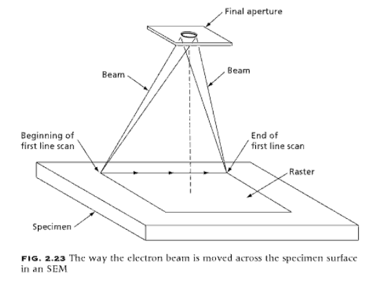
In
the part of the specimen surface used to form the image, that is, the raster,
the elec-tron beam is swept along a straight line over the entire width of the
raster, as indicated in Fig. 2.23. As the beam moves across the line, the
strength of the secondary electron emission from the surface is measured by the
detector and is used to control the brightness of the synchronized spot on the
cathode ray tube used to view or record the image. When the electron beam
completes its line scan at the far end of the raster, it is returned quickly to
the other side of the raster and to a point just below the start of the first
line. During the time of its return, the beam of the cathode ray tube is turned
off. By repeating this line scan-ning process, the entire surface of the raster
can be surveyed. The typical SEM uses 1000 line scans to form a 10 x 10 cm
image. A CRT screen with a long persistence phosphor is used so that the image
will last long enough tor the eye to be able to see a complete picture without
problems of fading. The complete scanning process is repeated every thirtieth
of a second, which conforms well to the one-twenty-fourth of a second frame
time of a inotion picture. To obtain a permanent photographic record of the
image, on the other hand. a cathode ray tube with a shun persistence phosphor
is used. This avoids overlapping of images Iron, adjacent lines.

(Reza Abbaschian,Lara
Abbaschian,Robert E. Reed-Hill, Physical Metallurgy Principles, PG.48)
POLYMER ADDITIVES
Group: material
There is no old definition
New definition:
A
polymer seldom is sold as a pure material. More often a polymer contains
several additives to aid during processing, add color, or enhance the
mechanical properties.
Plasticizers
Solvents,
commonly called plasticizers, am sometimes mixed into a polymer to dramatically
alter its theological or mechanical properties. Plasticizers are used as
processing aids since they have the same effect as raising the temperature of the
material. The resulting lowered viscosities reduce the risk of thermal
degradation during processing. For example. cellulose nitrite thermally
degrades if it is processed without a plasticizer. Plasticizers are more
commonly used to alter a polymer's mechanical properties such as stiffness,
toughness, and strength. For example, adding a plasticizer such as
dioctylphthalate (DOP) to PVC can reduce its stiffness by three orders of
magnitude and can lower its glass transition temperature by 35 °C. In fact,
highly plasticized PVC is rubbery at room temperature.
Flame Retardants
Since
polymers are organic materials, most of them arc flammable. The flammability of
polymers has always been a serious technical problem. However. some additives
that contain halogens, such as bromine or chlorine or phosphorous. reduce the
possibility of either ignition within a polymer component or once ignited,
flame spread. Bromine is more effective flame retardant than chlorine.
Stabilizers
The
combination of heat and oxygen can result in thermal degradation in a polymer.
Heat or energy produce free radicals which react with oxygen to form carbonyl
compounds, giving rise to yellow or brown discolorations in the final product.
Thermal degradation can be suppressed by adding stabilizers, such as
antioxidants or peroxide decomposers. These additives do not eliminate thermal
degradation but slow it down. Once the stabilizer has been consumed by reaction
with oxygen, the polymer is no longer protected against thermal degradation. Polyvinyl
chloride is probably the polymer most vulnerable to thermal degradation. In
polyvinyl chloride, scission of the C-CI bond occurs in the weakest point of
the molecule. The chlorine radicals react with their nearest CH group, forming
HCI and creating new weak C-CI bonds. A stabilizer must therefore he used to
neutralize HCI and stop the autocatalytic reaction, as well as preventing
corrosion of processing equipment.
Antistatic Agents
Since
polymers have such low electrical conductivity, they can easily build-up
electric charges. The amount of charge build-up is controlled by the rate at
which the charge is generated compared to the charge decay. The rate of charge
generation at the surface of the component can be reduced by reducing the
intimacy of contact. whereas the rate of charge decay is increased through
surface conductivity. }fence, a good antistatic agent should be an ionizable
additive that allows the charge to migrate to the surface. At the same time it
should be creating bridges to the atmosphere through moisture in the
surroundings. Typical antistatic agents are nitrogen compounds, such as long
chain amines, and amides and polyhydric alcohols.
Fillers
Fillers
can be classified three ways: those that reinforce the polymer and improve its
mechanical performance: those used to take-up space and so reduce the amount of
resin to produce a part - sometimes referred to as extenders: and those, less
common, that are dispersed through the polymer to improve its electric
conductivity. Polymers that contain fillers that improve its mechanical
performance are often referred to as reinforced plastics or composites.
Composites can be furthermore divided into composites with high performance
reinforcements, and composites with low pelfOrmance reinforcements. The high
performance composites are those where the reinforcement is placed inside the
polymer so that optimal mechanical behavior is achieved, such as unidirectional
glass fibers in an epoxy resin. High performance composites usually have 50 to
80% reinforcement by volume and usually have a laminated tubular shape
containing braided reinforcements. The low performance composites are those
where the reinforcement is small enough that it can be well dispersed into the
matrix. These materials can be processed the same way as their unreinforced
counterparts. The most common filler used to reinforce polymeric materials is
glass fiber. However, wood fiber, which is commonly used as an extender, also
increases the stiffness and mechanical performance of some thermoplastics. To
improve the bonding between the polymer matrix and the reinforcement, coupling
agents such as silanes and liteuzates are often added. Extenders, used to
reduce the cost of the component, are often particulate fillers. The most
common of these arc calcium carbonate, silica flour, clay, and wood flour or
fiber. As mentioned earlier, some fillers also slightly reinforce the polymer
matrix, such as clay, silica flour, and wood fiber. Polymers with extenders
often have significantly lower toughness than when unfilled.
Blowing Agents
The
task of blowing or foaming agents is to produce cellular polymers, also called expanded plastics. The cells can
he completely enclosed (closed cell) or can he interconnected (open cell).
Polymer foams are produced with densities between 1.6 kg/m3 and 960 kg/m3.
There are many reasons for using polymer foams, such as their high strength to
weight ratio, excellent insulating and acoustic properties, and high energy and
vibration absorbing properties.
Polymer
foams can be made by mechanically whipping gases into the polymer, or by either
chemical or physical means. The basic steps of the foaming process arc (1) cell
nucleation. (2) expansion or growth of the cells and (3) stabilization of the
cells. Cell nucleation occurs when, at a given temperature and pressure, the
solubility of a gas is reduced, leading to saturation, and expelling the excess
gas to form bubbles. Nucleating agents are used for initial formation of a
bubble. The bubble reaches an equilibrium shape when the pressure in the bubble
balances the surface tension.
(Tim A. Osswald, Polymer
Processing Fundamentals, pg.15-17)
Müge yapmış olduğun tanımlar çok iyi ama bir hafta içinde benden 3 kelime cevapladığın için yeni kural gereği malesef birinden puan alamayacaksın.
ReplyDelete