
Clapper Gripper
The clapper gripper is a popular design, favored because of its easy construction and simple mechanics. You can build the clapper using metal, plastic, wood, or a combination of all three.The clapper consists of a wrist joint (which, for the time being, we’ll assume is permanently attached to the forearm of the robot). Connected to the wrist are two plastic plates. The bottom plate is secured to the wrist; the top plate is hinged. A small spring-loaded solenoid is positioned inside, between the two plates. When the solenoid is not activated, the spring pushes the two flaps out, and the gripper is open. When the solenoid is activated, the plunger pulls in, and the gripper closes. The amount of movement at the end of the gripper is minimal—about 1⁄2 in with most solenoids. However, that is enough for general gripping tasks.
(G. McCOMB, M. PREDKO, ROBOT BUILDER’S BONANZA 3th ed., pg. 483-484)
Breadboard
The term breadboard is used for a variety of experimenter wired circuit products. In this
book, the term will be used to describe the temporary prototyping circuit platform shown
in Fig. 7-3 in which the holes are connected to adjacent ones by a spring-loaded connector. The typical arrangement is to have the interior holes connected outward while the outside rows of holes are connected together to provide a bus structure for power and common signals. Wire (typically 22 gauge) and most electronic components can be pushed into the circuit to make connections and, when the application is finished, to pull out for reuse.
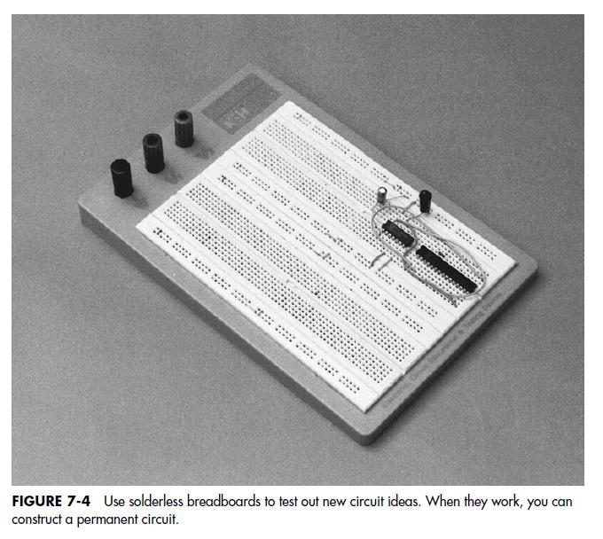
Breadboards are engineered to enable you to experiment with a circuit, without the trouble
of soldering. When you are assured that the circuit works, you may use one of the other
four construction techniques described in this chapter to make the design permanent. A
typical solderless breadboard mounted on a metal carrier is shown in Fig. 7-4. Breadboards are available in many different sizes and styles, but most provide rows of common tie points that are suitable for testing ICs, resistors, capacitors, and most other components that have standard lead diameters.
(G. McCOMB, M. PREDKO, ROBOT BUILDER’S BONANZA 3th ed., pg. 84)
Acetal daha önce başka bir arkadaşınız tarafından cevaplandırılmış lütfen değiştirin...
ReplyDeleteThis comment has been removed by the author.
ReplyDeleteAncillary equipment i de ben yapmıştım
ReplyDelete