1) Eddy Current Testing (NDT Method)
Previous Definition (Better)
Previous Definition (Better)
Eddy-current testing uses electromagnetic induction to detect flaws in conductive materials. In a standart eddy current testing, a circular coil carrying current is placed proximity to the test specimen. The alternating current in the coil generates changing magnetic field which interact with the test specimen and generates eddy current. Variations in the phase and magnitude of these eddy currents can be monitored using a second "search" coil, or by measuring changes to the current flowing in the primary "excitation" coil. Variations in the electrical conductivity or magnetic permeability of the test object, or presence of any flaws, wiil cause a change in eddy current flow and a corresponding change in the phase and amplitude of the measured current.
Eddy-current testing can detect very small cracks in or near te surface of the material, the surfaces need minimal preparation, and physically copmlex geometries can be investigated. It is also useful for making electrical conductivity and coating thickness measurements.
(Effective Building Maintenance: Protection of Capital Assets, Herbert W. Stanford,Stanford III, Herbert W., p.74)
New Definition
The main applications of the eddy current technique are for the detection of surface or subsurface flaws, conductivity measurement and coating thickness measurement. The technique is sensitive to the material conductivity, permeability and dimensions of a product.
Eddy currents can be produced in any electrically conducting material that is subjected to an alternating magnetic field (typically 10Hz to 10MHz). The alternating magnetic field is normally generated by passing an alternating current through a coil. The coil can have many shapes and can between 10 and 500 turns of wire. The magnitude of the eddy currents generated in the product is dependent on conductivity, permeability and the set up geometry. Any change in the material or geometry can be detected by the excitation coil as a change in the coil impedance. The most simple coil comprises a ferrite rod with several turns of wire wound at one end and which is positioned close to the surface of the product to be tested. When a crack, for example, occurs in the product surface the eddy currents must travel farther around the crack and this is detected by the impedance change.
(M. Willcox, G. Downes, A Brief Description of NDT Techniques, p17)
2) Laser Doppler Vibrometer (Measurement)
Previous Definition
The Laser Doppler Vibrometer (LDV) is commonly used instrument to measure velocity in structures in a non-contact fashion. The LDV works by splitting a laser, inside the system, and sending one part of split beam to receptive surface (reference beam), with the other part of the split laser sent to the structure in question. This second laser, or measurement, beam reflects back to the LDV unit after hitting the point of interest. The velocity of structure changes the frequency of the measurement beam. The velocity is calculated by comparing the frequency of the reference and reflected beams.
(Development and verification of a computer vision technique to measure the response of civil structures, Glen R. Wieger,University of South Carolina. Civil Engineering, p.3)
New Definition (Better)
The Laser Doppler Vibrometer (LDV) operates by measuring the velocity of a point addressed by a focused laser beam, using the Doppler shift between the incident light and scattered light returning to the measuring instrument. This has the distinct advantages of avoiding loading the structure being tested and of allowing the point addressed to be easily altered, by interposing adjustable beam-directing mirrors. Advantage has been taken of the LDV to give a half-way house between the use of accelerometer arrays, which give FRFs at very limited numbers of points, and field measurements, which have a much higher spatial resolution. Response measurements can, with an LDV, be obtained successively at hundreds or thousands of designated points without any of the structural changes so often introduced by accelerometer loading, and without multi-channel instrumentation. One disadvantage of the LDV is that the unavoidable optical phenomenon of speckle noise means that, in a typical point-by-point LDV survey, the LDV signal is spoiled at a few points by "speckle drop-out" and some form of data smoothing may be necessary to give a true picture of the spatial mode shape.
(A.B. Stanbridge, D.J. Ewins, Modal Testing Using A Scanning Laser Doppler Vibrometer, p1)
3) Wollaston Process (Manufacturing)
Previous Definition

4) Coolidge Process (Manufacturing)
Previous Definition
3) Wollaston Process (Manufacturing)
Previous Definition
The modern field of powder metallurgy dates to the early nineteenth century, when there was a strong interest in the metal platinum. Around 1815, Englishman William Wollaston developed a technique for preparing platinum powders, compacting them under high pressure, and baking (sintering) them at red heat. The Wollaston process marks the beginning of powder metallurgy as it is practices today.
(Fundamentals of Modern Manufacturing: Materials, Processes, and Systems, Mikell P. Groover, p.346)
New Definition (Better)
Wollaston published a full account of the technical details of his process just before he died in 1828. The essential points are that the aqua regia used for dissolving the mineral should be dilute (about 50:so) to avoid dissolving the iridium. The yellow precipitate produced by salamoniac was to be well washed and then well pressed, before being gently heated at a low heat to produce platinum sponge. He emphasised that the heat must be only just enough to bring this about and, in any grinding required, the metal must on no account be burnished. He recognised the need to preserve in the sponge a certain virginity about its surfaces if the subsequent welding was to be successful. A century later his acumen in this respect provided a vital foundation for the science of powder metallurgy. Having got his sponge into a fine and uniform powder by hand-rubbing, he washed and elutriated it thoroughly with water. After pouring off the excess of this, he transferred the metal mud to a brass mould and then closed tlis with a steel stopper wrapped in blotting-paper and topped with some wool, which allowed the excess water to escape under hand-pressure, A plate of copper was then put on top and the whole introduced into a powerful horizontal press of his own design. This produced a hard cake of metal which was next exposed to the greatest heat that he could obtain and then forged by hand on an anvil. An ingot of about 20 oz of malleable platinum resulted and this could be hammered into sheet or drawn into wire. Such was the material which Wollaston and his fabricators used for their articles for sale. He himself used the full procedure throughout the rest of his working life.

(D. McDonald, The Production of Malleable Platinum, p.105)
4) Coolidge Process (Manufacturing)
Previous Definition
In 1908, William Coolidge developed a procedure that made production of tungsten incandescent lamp filaments feasible. In this process, fine powders of tungsten oxide were reduced to metallic powders, pressed into compacts, presintered, hot-forged into rounds, sintered and finally drawn into filament wire. The Coolidge process is still used today to make filaments for incandescent light bulbs.
(Fundamentals of Modern Manufacturing: Materials, Processes, and Systems, Mikell P. Groover, p.346)
New Definition (Better)
This process consisted in incorporating tungsten powder with a ductile metal alloy of cadmium, bismuth and mercury, Squirting the mixture through a suitable die and then, by heat treatment, removing the foreign ingredients and sintering the tungsten powder. This, so-called, amalgam process was subsequently used in preparing thick tungsten filaments from which the first tungsten wire was drawn. As the amalgam process gave better squirted filaments, in the large sizes, than were at the time obtainable in any other way, it was intensively developed by Dr. Coolidge in the laboratories and later became the standard factory process for the production of high wattage and series lamp filaments.
Early in 1907, Dr. Coolidge again took up the hot working of tungsten, experimenting with a small rolling mill such as is used by jewelers. He heated the rolls, a most unusual operation, to a temperature of about 300 degrees Centigrade and passed amalgam process tungsten filaments between the hot rolls, obtaining an appreciable lengthening of the filaments. Before this time he had discovered that he could bend amalgam process filaments into special shapes by the application of proper but relatively low temperatures, going so far as to coil the filament into a spiral whose internal diameter was no greater than that of a knitting needle. This in itself was a valuable achievement, as such concentrated filaments are of value in focusing types of lamps such as those used in automobile headlights.
(W. Howell,H. Schroeder, History of The Incandescent Lamp, p.102)
5) Abrasive Flow Machining (Surface Cleaning)
Previous Definition
5) Abrasive Flow Machining (Surface Cleaning)
Previous Definition
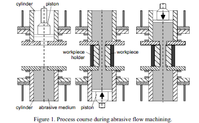
Abrasive flow machining (AFM) is an innovative finishing and polishing operation with a gentle material removal mechanism. In contrast to other machining methods for deburring and polishing, it is possible to machine difficult-to-access cavities, inner contours and undercuts in a reproductible manner. Typical components that could be machined by AFM are extrusion and compression molding dies as well as crimping and stamping tools. Use of AFM on these tools showed that within 2 minutes processing time an improvement of the surface roughness from Ra=2µm to Ra=0.2µm could be achieved.
(Aurich, J. C., Dornfeld, D., Burrs - Analysis, Control and Removal, p.73)
New Definition (Better)
Abrasive flow machining (AFM) is a process for the production of excellent surface qualities of inner profiles that are difficult to access and outside edges, as well as for deburring and edge rounding. The grinding medium used in AFM consists of a polymer fluid, the so-called base, in which the abrasive grains are bound. The grinding medium is pressed along the contours at a defined pressure and temperature. Depending on the respective machining task, different specifications of media are used. The description of process-related metrial removal mechanisms requires the knowledge of material removal mechanisms in AFM. Based on findings in flow mechanism, analyses have been made on material removal mechanisms.

(H. Szulczynsk, U. Eckart, Material Removal Mechanisms in Abrasive Flow Machining, p.1)
No comments:
Post a Comment