[Old]
Electronic gages are family of measuring and gaging instruments based on transducers capable of converting a linear displacement into electrical signal.The electrical signal is then amplified and transformed into a suitable data format such as a digital readout.Applications of electronic gages have grown rapidly in recent years driven by advances in microprocessor technology.They are gradually replacing many of the conventional measuring and gaging devices.Advantages of electronic gages include
-good sensivity, accuracy,precision,repeatability and speed of response
-Ability to sense very small dimensions
-ease of operation
-reduced human error
-electrical signal that can be displayed in various formats
-capability to be interfaced with computer systems for data processing.
(Fundamentals of modern manufacturing:materials,models and systems 4th edition, P.Groover, p.84-85)
[New][Better]
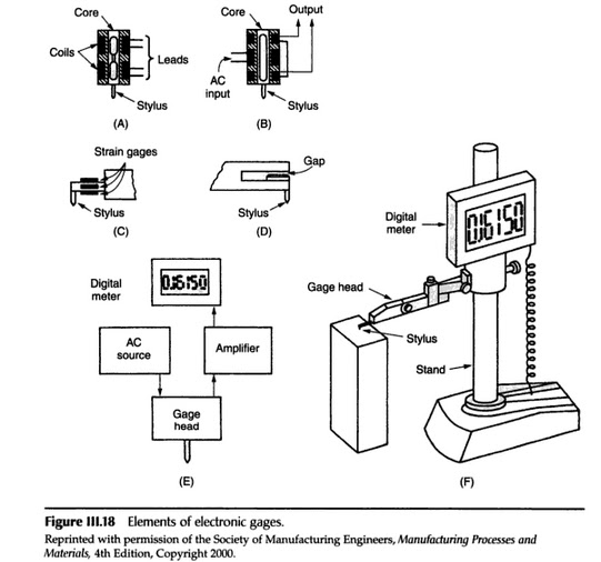
An electronic gage gives a reading in proportion to the amount a stylus is displaced. It may also actıate switches electronically to control various functios. Figure III.18 shows an example of an electronic gage, and diagrams of the most common kinds of gage heads. The variable inductance-bridge transducer has an alternating current fed into two coils connected into a bridge circuit. The reactance of each coil is changed as the position of the magnetic core is changed. This changes the output of the bridge circuit. The variable transformer or linear variable displacement transformer (LVDT) transducer has two opposed coils into which currents are induced from a primary coil. The net output depends on the displacement of the magnetic core. The deflection of a strain gage transducer is sensed by the changes in length and resistance of strain gages on its surface. This is also means for measuring force. Displacement of a variable capacitance head changes the air gap between plates of a condense connected in a bridge circuit. Un every case, an alternating current is fed into the gage as depicted in Figure III.18e. The output of the gage head circuit amplified electroniclly and displayed on a dial or digital readout. In some cases, the information from the gage may be recorded on tape or stored in a computer.
Electronic gages have several advantages: they are very sensitive; out put can be amplified as much has desired; a high-quality gage is quite stable; and they can be used as an absolute measuring device for thin pieces up to the range of the instrument. The amount of amplification can be switched easily, and three or four ranges are common for one instrument. Two or more heads may be connected to one amplifier to obtain sums or differences of dimensions, as for checking thickness, parallelism, and so on.
The certified quality technician handbook,Donald W. Benbow,Ahmad K. Elshennawy,H. Fred Walker,2003,pp.89-91
2)Manuel Part Programming: [Group: Manufacture Program]
[Old]
Done by a computer is called CAP.Sometimes a manuel program is entered into the machiner's controller via its own keypad.This is known as a manual data input.(Computer Numerical Control,Warren S. Seames)
[New][Better]
The program for machining a particular workpiece not only depends from person to person, but also varies from machine to machine. Different controllers use different syntax in instructing the machine tools. However, there are similarities between the codes and by understanding the basics of the codes, one can easily adpt to other controllers with minor changes.For simple components, part programming can be easily managed manually. It is essenatial that the programmer understands the various processes involved, by carefully studying the drawings, fixture and machine tool details. The programmer should also be aware of the various axes of the machine tool and the spindle speeds and feed rates possible on any particular machine. With this information, the programmer writes a code, which is then punched on a paper tape. The tape is then fed to the tape reader connected with the MCU. With this, the machine would be ready to manufacture as per the instructions punched on the tape. A typical block diagram of this process is shown in Fig. 8.1.1.


No comments:
Post a Comment