1) Mechanic Pulverization (Pulverization)
Previous Definition
The method involves breaking down of metals into small particles through
crushing and milling in ball mills. The method is used for brittle
metals only such as antimony and is not suitable for ductile metals like
steels and other non-ferrous metals, as they do not get properly
powdered and tend to take the form of flakes due to crushing action in
ball mills.
(Manufacturing Processes Second Edition, Yazar: J. P. Kaushish, Page 736)
New Definition (Better)
(Manufacturing Processes Second Edition, Yazar: J. P. Kaushish, Page 736)
New Definition (Better)
The goal of mechanical pulverization is to reduce the particle sizes of the biomass, as increased surface area leads to improved cellulose hydrolysis. Some of the crystalline structure of cellulose is also destroyed using these methods, though the amount varies according to the type of biomass and power applied in milling or grinding. A vibration ball mill is the most effective mechanical tool for breaking the crystalline structure of cellulose. Mechanical pulverization methods generally are high cost and do not remove the lignin or hemicellulose.
(A. Bin Abdullah, The Treatment of Sugar Cane Bagasse for Subsequent Use as Substrate for Cellulase Production by Aspergillus Terreus, p.8)
2) Part-Shaping Processes (Manufacturing)
Previous Definition
Part-shaping operations apply mechanical force and/or heat or other forms and combination of energy to change the geometry of the work material. There are various ways to classify these processes. The classification used here is based on the state of the starting material. There are four categories.
1. Solidification processes
2. Particulate processing
3. Deformation processing
4. Material removal processes
Groover M. P., Automation, production systems, and computer-integrated manufacturing, Ed. 3rd, p. 32)
New Definition (Better)
Common forming processes
Blanking and piercing. As sheet is usually delivered in large coils, the first operation
is to cut the blanks that will be fed into the presses; subsequently there may be further
blanking to trim off excess material and pierce holes. The basic cutting process is shown
in Figure I.1. When examined in detail, it is seen that blanking is a complicated process of
plastic shearing and fracture and that the material at the edge is likely to become hardened
locally. These effects may cause difficulty in subsequent operations and information on
tooling design to reduce problems can be found in the appropriate texts.

Bending. The simplest forming process is making a straight line bend as shown in
Figure I.2. Plastic deformation occurs only in the bend region and the material away
from the bend is not deformed. If the material lacks ductility, cracking may appear on

the outside bend surface, but the greatest difficulty is usually to obtain an accurate and
repeatable bend angle. Elastic springback is appreciable.
Various ways of bending along a straight line are shown in Figure I.3. In folding (a), the
part is held stationary on the left-hand side and the edge is gripped between movable tools
that rotate. In press-brake forming (b), a punch moves down and forces the sheet into
a vee-die. Bends can be formed continuously in long strip by roll forming (c). In roll
forming machines, there are a number of sets of rolls that incrementally bend the sheet,
and wide panels such as roofing sheet or complicated channel sections can be made in
this process. A technique for bending at the edge of a stamped part is flanging or wiping
as shown in Figure I.3(d). The part is clamped on the left-hand side and the flanging tool
moves downwards to form the bend. Similar tooling is used is successive processes to
bend the sheet back on itself to form a hem.

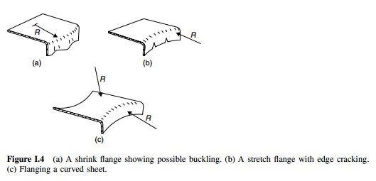
If the bend is not along a straight line, or the sheet is not flat, plastic deformation occurs
not only at the bend, but also in the adjoining sheet. Figure I.4 gives examples. In shrink
flanging (a), the edge is shortened and the flange may buckle. In stretch flanging (b), the length of the edge must increase and splitting could be a problem. If the part is curved
near the flange or if both the flange and the part are curved, as in Figure I.4(c), the flange
may be either stretched or compressed and some geometric analysis is needed to determine
this. All these flanges are usually formed with the kind of tooling shown in Figure I.3(d).
Section bending. In Figure I.5, a more complicated shape is bent. At the left-hand end
of the part, the flange of the channel is stretched and may split, and the height of the leg,
h, will decrease. When the flange is on the inside, as on the right, wrinkling is possible
and the flange height will increase.

Stretching. The simplest stretching process is shown in Figure I.6. As the punch is pushed
into the sheet, tensile forces are generated at the centre. These are the forces that cause the
deformation and the contact stress between the punch and the sheet is very much lower
than the yield stress of the sheet.
The tensile forces are resisted by the material at the edge of the sheet and compressive
hoop stresses will develop in this region. As there will be a tendency for the outer region to
buckle, it will be held by a blank-holder as shown in Figure I.6(b). The features mentioned
are common in many sheet processes, namely that forming is not caused by the direct

contact stresses, but by forces transmitted through the sheet and there will be a balance
between tensile forces over the punch and compressive forces in the outer flange material.
Hole extrusion. If a hole smaller than the punch diameter is first pierced in the sheet, the
punch can be pushed through the sheet to raise a lip as in the hole extrusion in Figure I.7.
It will be appreciated that the edge of the hole will be stretched and splitting will limit
the height of the extrusion.

Stamping or draw die forming. The part shown in Figure I.8(a) is formed by stretching
over a punch of more complicated shape in a draw die. This consists of a punch, and draw
ring and blank-holder assembly, or binder. The principle is similar to punch stretching
described above, but the outer edge or flange is allowed to draw inwards under restraint to
supply material for the part shape. This process is widely used to form auto-body panels
and a variety of appliance parts. Much of the outer flange is trimmed off after forming
so that it is not a highly efficient process, but with well-designed tooling, vast quantities
of parts can be made quickly and with good dimensional control. Die design requires
the combination of skill and extensive computer-aided engineering systems, but for the
purpose of conceptual design and problem solving, the complicated deformation system
can be broken down into basic elements that are readily analysed. In this book, the analysis
of these macroscopic elements is studied and explained, so that the reader can understand
those factors that govern the overall process.
Deep drawing. In stamping, most of the final part is formed by stretching over the punch
although some material around the sides may have been drawn inwards from the flange. As

there is a limit to the stretching that is possible before tearing, stamped parts are typically
shallow. To form deeper parts, much more material must be drawn inwards to form the
sides and such a process is termed deep drawing. Forming a simple cylindrical cup is
shown in Figure I.9. To prevent the flange from buckling, a blankholder is used and the
clamping force will be of the same order as the punch force. Lubrication is important
as the sheet must slide between the die and the blankholder. Stretching over the punch
is small and most of the deformation is in the flange; as this occurs under compressive
stresses, large strains are possible and it is possible to draw a cup whose height is equal to
or possibly a little larger than the cup diameter. Deeper cups can be made by redrawing
as shown in Figure I.10.

Tube forming. There are a number of processes for forming tubes such as flaring and
sinking as shown in Figure I.11. Again, these operations can be broken down into a few
elements, and analysed as steady-state processes.
Fluid forming. Some parts can be formed by fluid pressure rather than by rigid tools.
Quite high fluid pressures are required to form sheet metal parts so that equipment can

be expensive, but savings in tooling costs are possible and the technique is suitable where
limited numbers of parts are required. For forming flat parts, a diaphragm is usually placed
over the sheet and pressurized in a container as in Figure I.12. As the pressure to form the
sheet into sharp corners can be very high, the forces needed to keep the container closed
are much greater than those acting on a punch in a draw die, and special presses are
required. Complicated tubular parts for plumbing fittings and bicycle frame brackets are
made by a combination of fluid pressure and axial force as in Figure I.13. Tubular parts,
for example frame structures for larger vehicles, are made by bending a circular tube,
placing it in a closed die and forming it to a square section as illustrated in Figure I.14.
Coining and ironing. In all of the processes above, the contact stress between the sheet
and the tooling is small and, as mentioned, deformation results from membrane forces in
the sheet. In a few instances, through-thickness compression is the principal deformation
force. Coining, Figure I.15, is a local forging operation used, for example, to produce a
groove in the lid of a beverage can or to thin a small area of sheet. Ironing, Figure I.16, is
a continuous process and often accompanies deep drawing. The cylindrical cup is forced
through an ironing die that is slightly smaller than the punch plus metal thickness dimension. Using several dies in tandem, the wall thickness can be reduced by more than one-half
in a single stroke.


(Z. Marciniak, J.L. Duncan, S.J. Hu, Mechanics of Sheet Metal Forming, p.xiii-xx)
Berk, Part-Shaping processes için daha genel bir tanım bulmalısın. Senin verdiğin tanımlar daha çok talaşsız imalat adına yazılmışlar. Geçmişteki tanıma da bakarsan talaşlı-talaşsız-toz metalurjisi vb birçok dalı içermesi lazım.
ReplyDeleteThis is a really informative knowledge, Thanks for posting this informative Information. Deep Drawing
ReplyDelete